
 My Inquiry
 My Account


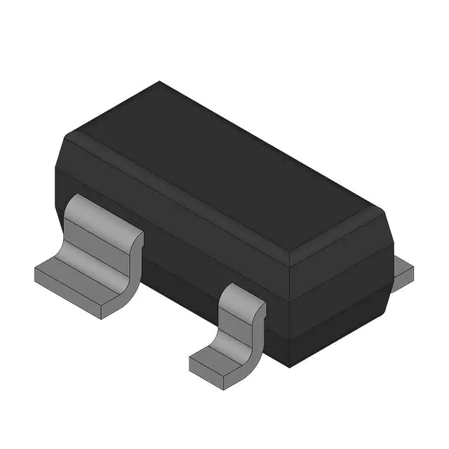
Renesas 3SK295ZQ-TL-E
- Part No.:
- 3SK295ZQ-TL-E
- Manufacturer:
- Renesas
- Category:
- FETs, MOSFETs
- Package:
- -
- Datasheet:
-
 3SK295ZQ-TL-E.pdf
- Description:
- SMALL SIGNAL N-CHANNEL MOSFET
- Quantity:
- Payment:

- Shipping:

Inventory:36,000
Please send an inquiry. Send us your inquiry, and we will respond immediately.
Product details
Overview
3SK295ZQ-TL-E from Renesas Electronics is a silicon N-channel dual-gate MOSFET designed for UHF RF amplification. It delivers a typical noise figure of 2.0 dB at 900 MHz, supports low-voltage operation (VDS = 4 V), and provides 19.5 dB power gain with 20.8 mS forward transfer admittance at 1 kHz under specified bias conditions.
For engineers reviewing the 3SK295ZQ-TL-E datasheet, 3SK295ZQ-TL-E pinout, 3SK295ZQ-TL-E application, or 3SK295ZQ-TL-E equivalent, key selection criteria include its dual-gate architecture for input impedance control, low-noise performance in 800–1000 MHz bands, gate voltage tolerance (±8 V), MPAK-4 surface-mount package, and suitability for compact UHF front-end designs requiring stable small-signal gain.
Technical Context
This device employs a dual-gate structure where Gate1 controls transconductance and input matching, while Gate2 sets DC bias and channel conductivity. Its low Crss (0.01–0.03 pF) minimizes feedback capacitance, enabling stable high-frequency amplification without external neutralization.
Designed for single-ended UHF amplifier stages, it operates with VDS up to 12 V and ID up to 25 mA, with thermal limits defined by a 150°C channel temperature and 150 mW channel power dissipation at 25°C ambient - derating linearly above 25°C per the published Pch vs. Ta curve.
Key Specifications
| Parameter | Value and Actual Design Meaning |
|---|---|
| Noise Figure | 2.0 dB typ. at 900 MHz - enables sensitive receiver front-ends in UHF ISM and cordless phone bands |
| Power Gain | 19.5 dB typ. at 900 MHz - delivers usable small-signal gain without cascading stages |
| Forward Transfer Admittance | 20.8 mS typ. at 1 kHz - ensures strong transconductance for high gain at RF frequencies |
| Reverse Transfer Capacitance | 0.01–0.03 pF - suppresses internal feedback, improving stability in tuned amplifiers |
| Drain-Source Voltage | 12 V max - supports operation from 3–6 V supply rails with headroom for signal swing |
| Input Capacitance | 1.5 pF typ. - facilitates impedance matching into 50 Ω systems using minimal external components |
| Package | MPAK-4 (PLSP0004ZA-A) - 3.0 × 1.95 mm surface-mount footprint for space-constrained RF modules |
Pinout & Package
3SK295ZQ-TL-E uses the MPAK-4 package (RENESAS code PLSP0004ZA-A), a 4-pin surface-mount plastic package with exposed drain pad for thermal enhancement. Pin 1 is Source, Pin 2 is Gate1, Pin 3 is Gate2, and Pin 4 is Drain - confirmed by outline diagram and marking "ZQ–" orientation on datasheet page 1.
| Pin/Terminal | Circuit Role | Design Meaning |
|---|---|---|
| 1 (Source) | Common reference node for both gates and drain | Connected to RF ground plane; serves as signal return path and thermal conduction path via exposed pad |
| 2 (Gate1) | Primary RF input control terminal | Accepts AC-coupled RF signal; bias set independently to optimize noise figure and input match |
| 3 (Gate2) | DC bias and channel conductivity control | Set to fixed DC potential (e.g., +3 V) to establish operating point; isolates bias from RF path |
| 4 (Drain) | RF output and power delivery node | Connected to tuned load or next stage; exposed pad enhances heat dissipation for 150 mW Pch rating |
Key Features
| Feature | Design Value |
|---|---|
| Dual-gate architecture | Enables independent optimization of RF input matching (via Gate1) and DC biasing (via Gate2), reducing need for neutralization networks |
| Low noise figure | 2.0 dB typ. at 900 MHz allows use in battery-powered UHF receivers where sensitivity is critical |
| Low-voltage operation | Full performance achieved at VDS = 4 V and VG2S = 3 V - compatible with 3.3 V system rails |
| ESD-sensitive handling | Marked as ESD-sensitive (HBM Class 1A); requires grounded workstations and anti-static packaging during assembly |
| Thermally enhanced package | MPAK-4 exposes drain metal on bottom side - improves thermal resistance to PCB for sustained 10 mA operation |
Applications
| UHF Wireless Microphones | Cordless Phone Base Stations |
|---|---|
Use Scenario: Amplifying weak 863–865 MHz microphone signals before downconversion in portable digital wireless mics. IC Role / Device Role / Timing Role: First-stage low-noise RF amplifier in receive chain; dual-gate structure isolates antenna input from bias network. Use Value: 2.0 dB NF preserves SNR in low-power handheld units; MPAK-4 footprint enables compact PCB layout near antenna feedpoint. | Use Scenario: Boosting 1.88–1.90 GHz DECT transmit/receive signals in residential base stations with multi-channel support. IC Role / Device Role / Timing Role: Low-noise receive amplifier (LNA) in diversity antenna paths; Gate2 biased for consistent gain across temperature. Use Value: 19.5 dB PG reduces need for additional gain stages; Crss < 0.03 pF ensures unconditional stability without external compensation. |
| ISM Band Sensor Transceivers | UHF RFID Reader Front-Ends |
Use Scenario: Signal amplification in 902–928 MHz industrial sensor nodes transmitting telemetry over long range. IC Role / Device Role / Timing Role: High-linearity LNA in battery-operated sensor gateway; dual-gate configuration rejects local oscillator leakage. Use Value: 20.8 mS |yfs| sustains gain under varying supply (3–4.2 V); Ciss = 1.5 pF simplifies matching to microstrip traces. | Use Scenario: Boosting weak backscatter signals from passive UHF RFID tags in warehouse portal readers. IC Role / Device Role / Timing Role: First-stage LNA in reader receive path; optimized for 900 MHz band with minimal external components. Use Value: Low 2.0 dB NF extends read range; S11 < –10 dB across 860–960 MHz eliminates need for tunable matching networks. |
Equivalent & Alternatives
The following parts are listed as comparable options for similar dual-gate MOSFET amplifier applications.
| Alternative Part | Technical Difference | Application Difference | Selection Advice |
|---|---|---|---|
| NE3210S | Higher NF (2.5 dB typ.), same MPAK-4 package, lower |yfs| (17 mS), higher VDS rating (15 V) | Better suited for higher-supply systems needing margin; slightly degraded noise-limited sensitivity | Select when 15 V rail availability justifies 0.5 dB NF penalty and higher breakdown margin |
| BF998 | Dual-gate N-channel MOSFET in SOT-343 package; NF = 1.7 dB typ., |yfs| = 25 mS, Crss = 0.02 pF | Smaller footprint but lower power handling (100 mW Pch); not rated for >125°C channel temp | Prefer for ultra-compact layouts where thermal load is below 10 mA and ambient stays < 85°C |
Compared with NE3210S and BF998, the 3SK295ZQ-TL-E offers the best balance of noise performance (2.0 dB), gain (19.5 dB), and thermal robustness (150°C Tch) in the MPAK-4 form factor - making it optimal for industrial UHF amplifiers requiring reliability across extended temperature ranges.
Availability
3SK295ZQ-TL-E is available at Aetrix Electronics and suitable for UHF wireless microphones, cordless phone base stations, ISM band sensor transceivers, and UHF RFID reader front-ends requiring stable component supply and RoHS-compliant packaging.
Supply support for 3SK295ZQ-TL-E includes scheduled delivery planning, volume procurement assistance, BOM continuity management, traceable sourcing, and lifecycle availability coordination for OEM customers, industrial embedded developers, connected-device designers, and electronics production programs.
Manufacturer
Renesas Electronics Corporation is a global semiconductor leader headquartered in Tokyo, Japan, specializing in microcontrollers, analog, power, and RF solutions for industrial, automotive, and consumer markets.
The 3SK295ZQ-TL-E belongs to Renesas' legacy RF transistor product line, engineered specifically for high-performance, low-noise UHF amplification in compact wireless infrastructure and portable communication devices.
FAQ
What is the maximum drain current rating for the 3SK295ZQ-TL-E?
The 3SK295ZQ-TL-E has an absolute maximum drain current (ID) rating of 25 mA at Ta = 25°C. Operation above this value risks thermal runaway or permanent degradation. Derating is required per the channel power dissipation curve - Pch drops linearly to zero at 150°C channel temperature. For continuous 10 mA operation, ensure PCB copper area and airflow maintain Tch ≤ 125°C. The 3SK295ZQ-TL-E datasheet specifies pulse test conditions for transient current peaks.
Does the 3SK295ZQ-TL-E require external neutralization for stability?
No, the 3SK295ZQ-TL-E does not require external neutralization due to its inherently low reverse transfer capacitance (Crss = 0.01–0.03 pF), which minimizes internal feedback. Stability is further enhanced by the dual-gate architecture that isolates RF input (Gate1) from DC bias (Gate2). Measured S-parameters confirm unconditional stability across 100–1000 MHz when properly decoupled and matched - verified in the 3SK295ZQ-TL-E datasheet Figures 5–8.
What is the recommended gate bias configuration for low-noise operation of the 3SK295ZQ-TL-E?
For minimum noise figure, bias Gate2 at +3.0 V and Gate1 at 0.5 V (DC), with VDS = 4.0 V and ID = 10 mA - matching the 3SK295ZQ-TL-E's NF = 2.0 dB typ. condition at 900 MHz. Gate1 must be AC-coupled; Gate2 requires low-impedance DC bias with ≥10 µF bypassing to ground. The 3SK295ZQ-TL-E's VG1S(off) range (–0.5 to +0.5 V) and VG2S(off) (0 to +1.0 V) allow precise setting of this operating point using resistive dividers or dedicated bias ICs.
Is the 3SK295ZQ-TL-E RoHS compliant and lead-free?
Yes, the 3SK295ZQ-TL-E is RoHS compliant and lead-free. Renesas confirms compliance with EU Directive 2011/65/EU (RoHS 2) in its environmental documentation, and the "-E" suffix in the part number denotes lead-free plating per JEDEC standard. The MPAK-4 package uses matte tin (Sn) termination with no lead content exceeding 0.1 wt%. Full material declarations and test reports for the 3SK295ZQ-TL-E are available through Renesas' compliance portal upon request.
How does electrostatic discharge sensitivity affect handling of the 3SK295ZQ-TL-E?
As stated in the 3SK295ZQ-TL-E datasheet, this device is highly ESD-sensitive (HBM Class 1A, < 250 V). Handling requires grounded wrist straps, conductive foam storage, ionized air workstations, and ESD-safe taping equipment. PCB assembly must use static-dissipative soldering irons and avoid ungrounded rework tools. Failure to observe these precautions may cause latent damage to Gate1 or Gate2 oxide layers - degrading NF or causing parametric shift. The 3SK295ZQ-TL-E marking "ZQ–" identifies the correct orientation to prevent misalignment-induced stress during pick-and-place.
3SK295ZQ-TL-E Specifications
- Product attributes
- Attribute value
- Manufacturer:
- Renesas
- Series:
- *
- Package/Case:
- -
- Packaging:
- Bulk
- Product Status:
- Active
- FET Type:
- -
- Technology:
- -
- Drain to Source Voltage (Vdss):
- -
- Current - Continuous Drain (Id) @ 25°C:
- -
- Drive Voltage (Max Rds On, Min Rds On):
- -
- Rds On (Max) @ Id, Vgs:
- -
- Vgs(th) (Max) @ Id:
- -
- Gate Charge (Qg) (Max) @ Vgs:
- -
- Vgs (Max):
- -
- Input Capacitance (Ciss) (Max) @ Vds:
- -
- FET Feature:
- -
- Power Dissipation (Max):
- -
- Operating Temperature:
- -
- Grade:
- -
- Qualification:
- -
- Mounting Type:
- -
- Supplier Device Package:
- -
3SK295ZQ-TL-E FAQ
1.How can I place an order for 3SK295ZQ-TL-E through Aetrix?
Please submit a Request for Quotation (RFQ) for 3SK295ZQ-TL-E on Aetrix. Our sales agent will provide a competitive quotation and guide you through the order confirmation once you accept the terms.
2.Are the price and stock information for 3SK295ZQ-TL-E reliable?
The price and inventory of 3SK295ZQ-TL-E are updated periodically and may fluctuate due to market conditions. Stock and pricing data are typically refreshed every 24 hours. Quotation validity for 3SK295ZQ-TL-E is usually 5 days.
3.What payment methods are accepted for 3SK295ZQ-TL-E?
We accept Wire Transfer, PayPal, Credit Card, Western Union, MoneyGram, and Escrow for 3SK295ZQ-TL-E transactions.
Note: Certain payment methods may incur a processing fee.
4.How is shipping managed for 3SK295ZQ-TL-E?
3SK295ZQ-TL-E orders can be shipped via leading logistics carriers, including DHL, UPS, FedEx, TNT, or Registered Mail.
Once your 3SK295ZQ-TL-E order is processed, you will receive an email with the shipment details and tracking number.
Note: Tracking information may take up to 24 hours to appear. Express delivery typically takes 3–5 business days.
5.How can I obtain technical support or documentation for 3SK295ZQ-TL-E?
For technical support, including 3SK295ZQ-TL-E datasheets, pinout diagrams, or application guidance, please contact our engineering support team. They can provide detailed documentation and assistance for your 3SK295ZQ-TL-E requirements.
6.How does Aetrix verify that 3SK295ZQ-TL-E is sourced from the original manufacturer or authorized distributors?
All 3SK295ZQ-TL-E products on Aetrix are procured from qualified distributors and authorized channels. Our dedicated quality assurance team conducts strict verification, including traceability checks and, if necessary, third-party testing. This ensures that 3SK295ZQ-TL-E meets industry standards.
7.What is the process for return or replacement of 3SK295ZQ-TL-E?
All 3SK295ZQ-TL-E units undergo pre-shipment inspection (PSI). If there is an issue with 3SK295ZQ-TL-E, returns or replacements are accepted under the following conditions:
1.Quantity discrepancies, incorrect items, or visible external defects (such as breakage or corrosion), acknowledged by Aetrix.
2.The issue is reported within 90 days of delivery.
3.The 3SK295ZQ-TL-E part is unused and in its original packaging.
Return procedure for 3SK295ZQ-TL-E:
1.Submit a request within 90 days.
2.Obtain a Return Material Authorization (RMA) from Aetrix.
3SK295ZQ-TL-E Tags
-
BSZ180P03NS3EGATMA1
Infineon Technologies
-
SIRA14DP-T1-GE3
Vishay Siliconix

-
AO4419
Alpha & Omega Semiconductor Inc.
-
SISA14BDN-T1-GE3
Vishay Siliconix
-
PSMN9R5-30YLC,115
Nexperia USA Inc.
-
BUK9Y21-40E,115
Nexperia USA Inc.
-
RTQ035N03HZGTR
Rohm Semiconductor
-
FDMS7680
onsemi
-
RQ3E180BNTB
Rohm Semiconductor
-
STL6N2VH5
STMicroelectronics
-
DMPH4029LFGQ-7
Diodes Incorporated
-
DMT6015LSS-13
Diodes Incorporated
Tech Hub

TTL and CMOS logic families differ in thresholds, loading, output drive, power and timing. This engineering guide compares 74HC and 74HCT, calculates noise margins and checks 3.3 V/5 V compatibility.

A practical engineering guide to 3.3V and 5V logic compatibility, input thresholds, resistor dividers, translator ICs, MOSFET level shifting, I2C pull-ups, timing limits and power-sequencing risks.

The 74HC595 uses push-pull logic outputs, while the TPIC6B595 uses 50 V open-drain DMOS sinks for higher-power loads. This guide compares timing, current limits, 3.3 V interfacing, load wiring, thermal…

The 74HC595 converts serial data into eight stable parallel outputs. This guide covers pin functions, shift and storage timing, OE and MR behavior, drive-current limits, cascading, voltage compatibilit…

A technical comparison of level-sensitive latches and edge-triggered flip-flops, covering timing windows, setup and hold limits, master–slave operation, time borrowing, race-through, HDL inference and…

A D latch stores one bit while Enable controls when data can pass. This reference covers gate-level operation, truth tables, transparency, setup and hold timing, LE versus OE, common ICs and practical …

An SR latch stores one bit through cross-coupled feedback. This engineering reference covers NOR and NAND implementations, truth tables, forbidden-state recovery, gated operation, switch debouncing, fa…

Latch circuits retain one bit through feedback. This technical reference covers SR and D latches, truth tables, transparency, timing limits, latch-versus-flip-flop behavior, applications and common log…

An engineering guide to LED driver operation, constant-current and constant-voltage outputs, linear and switching topologies, dimming, IC selection, calculations, replacement compatibility, and fault c…

Operational amplifier guide covering op amp basics, feedback, ideal vs real op amps, common configurations, buffer circuits, offset, bias current, gain-bandwidth, slew rate, rail-to-rail limits and sel…


