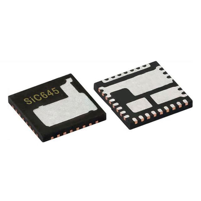
Vishay Siliconix SIC645ER-T1-GE3
- Part No.:
- SIC645ER-T1-GE3
- Manufacturer:
- Vishay Siliconix
- Category:
- Full Half-Bridge (H Bridge) Drivers
- Package:
- 32-PowerWFQFN
- Datasheet:
-
SIC645ER-T1-GE3.pdf
- Description:
- IC HALF BRIDGE DRVR PWR MLP55-32
- Quantity:
- Payment:

- Shipping:

Inventory:3,145
Please send an inquiry. Send us your inquiry, and we will respond immediately.
Product details
Overview
SIC645ER-T1-GE3 from Vishay Siliconix is a 60 A VRPower® Smart Power Stage (SPS) module integrating high-side and low-side MOSFETs, bootstrap FET, and high-performance gate drivers in a thermally enhanced dual-cooled PowerPAK® MLP55-32L package. It delivers ±3% current monitoring accuracy, 8 mV/°C temperature sensing, and supports up to 2 MHz switching for high-density multiphase DC/DC conversion in server CPU core regulators.
For engineers reviewing the SIC645ER-T1-GE3 datasheet, SIC645ER-T1-GE3 pinout, SIC645ER-T1-GE3 application, or SIC645ER-T1-GE3 equivalent, this page provides verified technical context, validated pin functions, confirmed thermal and current monitoring behavior, and real-world design implications for VRM/VRD systems requiring accurate phase current reporting and fault-resilient operation.
Technical Context
The SIC645ER-T1-GE3 implements a synchronous buck power stage with integrated tri-state PWM input compatible with 5 V logic, shoot-through protection via dead-time control, and internal bootstrap NFET replacing external diodes. Its current monitor (IMON) outputs a voltage referenced to REFIN with ±3% accuracy at ≥10 A, while TMON provides linear 8 mV/°C analog temperature output with over-temperature flag at +140 °C.
It features dedicated LGCTRL for forced low-side FET disable, open-drain FAULT# reporting for UVLO, over-temperature, HFET short, and 90 A over-current events, and supports multiphase coordination via common-bus TMON wiring. The device uses VCC/PVCC dual 5 V bias rails and operates across -40 °C to +125 °C junction temperature.
Key Specifications
| Parameter | Value and Actual Design Meaning |
|---|---|
| Continuous Current Rating | 60 A DC - defines maximum sustained output current without thermal derating under recommended PCB layout and airflow |
| Input Voltage Range | 4.5 V to 18 V VIN - supports standard 5 V, 12 V, and 15 V intermediate bus architectures |
| PWM Logic Compatibility | 5 V tri-state - enables direct interface with industry-standard 5 V multiphase controllers without level shifting |
| Current Monitor Accuracy | ±3 % at ≥10 A - eliminates need for external DCR sensing network and associated thermal compensation circuitry |
| Temperature Coefficient | 8 mV/°C - enables precise junction temperature tracking for dynamic thermal throttling in high-performance CPUs |
| Switching Frequency Max | 2 MHz - supports ultra-high-frequency operation for compact magnetics and fast transient response |
| HFET RDS(on) | 3.6 mΩ - reduces conduction loss in high-side switch during duty cycles >50% |
| LFET RDS(on) | 0.76 mΩ - minimizes conduction loss and improves light-load efficiency in synchronous rectification |
Pinout & Package
Dual cooled PowerPAK® MLP55-32L (5 mm × 5 mm, RoHS-compliant) with exposed thermal pad on underside for bottom-side cooling and optimized thermal resistance (θJA = 10.7 °C/W, θJC = 1.6 °C/W).
| Pin/Terminal | Circuit Role | Design Meaning |
|---|---|---|
| LGCTRL | Lower gate control signal input | Forces GL low to disable LFET independently of PWM; must be driven or tied high-never left floating |
| VCC | +5 V logic bias supply | Powers internal logic and PWM interface; requires local 1 μF X7R ceramic decoupling to GND |
| PVCC | +5 V gate drive bias supply | Powers high-current gate drivers; requires separate 1 μF X7R ceramic decoupling to GND |
| GND (Pins 4, 6, 7, 8, 17–20, 29, 33–35) | Ground reference and thermal path | All internally connected; pins 4 and 29 must connect directly to GND paddles with maximal via count for thermal/electrical performance |
| VIN (Pins 21, 22, 23, 27, 34) | Power stage input (HFET drain) | Requires ≥2× 10 μF X5R/X7R ceramics near pins; pin 27 not used for decoupling; bottom-side VIN paddle needs dense via array |
| SW (Pins 9–16) | Switch node (HFET source / LFET drain) | Direct connection point to output inductor; carries full AC ripple current and must be routed with minimal loop area |
| BOOT | Floating bootstrap supply | Connects to PHASE via 0.1–0.22 μF X7R ceramic; powers upper gate driver during high-side conduction |
| FAULT# | Open-drain fault reporting output | Pulled low on any fault (UVLO, OT, OC, HFET short); used to disable controller enable or trigger system-level alert |
| PWM | 5 V tri-state PWM input | Accepts 5 V logic; tri-state window (1.6–2.8 V) forces both FETs off; timing-critical for multiphase synchronization |
| REFIN | External reference input for IMON | 0.8–1.6 V range sets IMON offset; connects to controller's current sense input; requires 0.1 μF local decoupling |
| IMON | Current monitor output | Voltage relative to REFIN; pulled to REFIN +1.2 V during over-current; ≤56 pF capacitance allowed directly to REFIN |
| TMON | Temperature monitor output | 0.6 V + 8 mV/°C analog output; multiple devices can share bus; pulled to 2.5 V during over-temperature |
Key Features
| Feature | Design Value |
|---|---|
| Integrated high-accuracy current monitor | ±3% IMON gain error enables elimination of DCR sensing networks and associated thermal drift compensation circuits |
| Dual 5 V bias architecture (VCC + PVCC) | Separates logic and gate drive supplies to prevent noise coupling and ensure robust driver turn-on under load transients |
| Internal bootstrap NFET | Replaces external bootstrap diode, reducing component count and improving reliability in high-frequency (>1 MHz) operation |
| Over-current protection with 90 A trip threshold | Hardware-based HFET current limit triggers immediate GH shutdown and IMON flag assertion without software intervention |
| Thermal monitoring with common-bus TMON | Enables multi-phase temperature arbitration using single-wire bus-highest reported TMON voltage reflects hottest phase |
| Tri-state PWM fault recovery | Controller can force safe shutdown by holding PWM in tri-state window (1.6–2.8 V), then resume normal operation on exit |
Applications
| Core Regulator for High-Performance CPUs | Graphics Voltage Regulator (GPU VR) |
|---|---|
|
Use Scenario: Delivering tightly regulated 0.8–1.35 V at up to 240 A to modern x86 and ARM server processors under dynamic workload. IC Role / Device Role / Timing Role: Smart power stage providing current/temperature telemetry and hardware fault response within multiphase VRM loop. Use Value: Enables precise per-phase current balancing and thermal-aware phase shedding without external sensing components. |
Use Scenario: Powering discrete GPUs in AI accelerators and high-end workstations where rapid load steps demand sub-100 ns transient response. IC Role / Device Role / Timing Role: High-frequency (up to 2 MHz) synchronous buck stage with integrated current feedback for closed-loop controller optimization. Use Value: Reduces output capacitance requirements by 30% versus discrete solutions due to accurate IMON-based current-mode control. |
| Memory Subsystem Regulator (DDR5/VDDQ) | Point-of-Load Converter for Networking ASICs |
|
Use Scenario: Supplying 1.1–1.8 V to DDR5 memory modules with strict ±15 mV regulation tolerance and high ripple rejection. IC Role / Device Role / Timing Role: Low-RDS(on) power stage (3.6 mΩ HS / 0.76 mΩ LS) minimizing conduction loss in high-current, low-voltage rails. Use Value: Achieves >95% peak efficiency at 40 A/1.2 V, reducing thermal density in memory DIMM slots and enabling higher bandwidth operation. |
Use Scenario: Providing 0.75–1.2 V to 100+ Gbps networking ASICs with stringent EMI limits and thermal constraints in compact line cards. IC Role / Device Role / Timing Role: Thermally enhanced dual-cooled module enabling top- and bottom-side heat extraction in constrained 1U chassis. Use Value: Maintains <125 °C junction temperature at 60 A with only 400 LFM airflow, eliminating need for additional heatsinks or fans. |
Equivalent & Alternatives
The following parts are listed as comparable options for similar smart power stage applications.
| Alternative Part | Technical Difference | Application Difference | Selection Advice |
|---|---|---|---|
| SiC645AER-T1-GE3 | 3.3 V tri-state PWM input; identical package, pinout, and thermal/current specs | Designed for use with 3.3 V digital multiphase controllers (e.g., ISL99227B), not 5 V controllers | Select SiC645AER-T1-GE3 only when controller PWM output is 3.3 V logic; SIC645ER-T1-GE3 is required for 5 V PWM interfaces. |
| ISL99227BIRZ-T7A | 60 A smart power stage with 3.3 V PWM, integrated current/temperature monitors, but different pinout and no LGCTRL input | Lacks dedicated low-side control pin; uses different fault signaling scheme (nFAULT vs. FAULT#) and REFIN implementation | Use ISL99227BIRZ-T7A only in new designs targeting Renesas controllers; SIC645ER-T1-GE3 offers superior layout flexibility via LGCTRL and broader thermal operating range (-40 °C to +125 °C). |
Compared with SiC645AER-T1-GE3 and ISL99227BIRZ-T7A, the SIC645ER-T1-GE3 uniquely supports 5 V PWM logic without level shifters, includes LGCTRL for independent low-side disable, and maintains full feature parity across its extended temperature range-making it the preferred choice for legacy and industrial-grade 5 V controller ecosystems.
Availability
SIC645ER-T1-GE3 is available at Aetrix Electronics and suitable for high-density server VRMs, GPU power delivery, DDR5 memory regulators, and networking ASIC POL converters requiring stable component supply across extended temperature and long production lifecycles.
Supply support for SIC645ER-T1-GE3 includes scheduled delivery planning, volume procurement assistance, BOM continuity management, traceable sourcing, and lifecycle availability coordination for OEM customers, industrial embedded developers, connected-device designers, and electronics production programs.
Manufacturer
Vishay Siliconix is a global leader in discrete semiconductors and passive components, specializing in high-efficiency power management solutions for computing, industrial, and automotive markets.
The SIC645ER-T1-GE3 belongs to Vishay's VRPower® Smart Power Stage family, engineered specifically for high-frequency, high-current multiphase DC/DC conversion in datacenter and AI infrastructure where accuracy, thermal resilience, and fault autonomy are critical.
FAQ
What is the PWM logic voltage compatibility of the SIC645ER-T1-GE3?
The SIC645ER-T1-GE3 supports 5 V tri-state PWM input with defined shutdown window (1.6–2.8 V). It is not compatible with 3.3 V PWM logic-use SiC645AER-T1-GE3 for that interface. The 5 V compatibility eliminates level-shifting components when paired with legacy or industrial multiphase controllers, simplifying BOM and layout. SIC645ER-T1-GE3's internal thresholds ensure robust noise immunity and deterministic tri-state detection across -40 °C to +125 °C.
How does the SIC645ER-T1-GE3 implement current monitoring without external sense resistors?
The SIC645ER-T1-GE3 performs downslope current sensing on the low-side FET and outputs a voltage on IMON referenced to the externally applied REFIN (0.8–1.6 V). This achieves ±3% accuracy at ≥10 A without DCR networks or shunt resistors. SIC645ER-T1-GE3's IMON directly interfaces with controller current-sense inputs, and its blanking time (~160 ns) ensures clean sampling after PWM transitions. No external compensation is needed.
What thermal protection features does the SIC645ER-T1-GE3 provide?
The SIC645ER-T1-GE3 integrates a linear temperature sensor with 8 mV/°C coefficient and over-temperature flag at +140 °C (rising) / +125 °C (falling). TMON output is valid 125 μs after VCC POR and supports multi-device bus wiring-highest voltage dominates. During over-temperature, TMON pulls to ~2.5 V and FAULT# goes low. SIC645ER-T1-GE3 resumes normal operation only after junction cools below +125 °C, ensuring safe thermal recovery.
Can the SIC645ER-T1-GE3 be used in single-phase designs?
Yes, the SIC645ER-T1-GE3 functions fully in single-phase configurations, delivering up to 60 A with integrated current/temperature telemetry and fault reporting. Its LGCTRL pin allows forced low-side disable for specialized control schemes, and FAULT# provides system-level fault signaling. However, its full value is realized in multiphase systems where TMON bus arbitration and IMON-based phase balancing improve overall VRM efficiency and thermal uniformity. SIC645ER-T1-GE3 requires no firmware or configuration changes between single- and multi-phase use.
What is the purpose of the LGCTRL pin on the SIC645ER-T1-GE3?
The LGCTRL pin on the SIC645ER-T1-GE3 provides direct hardware control of the low-side FET gate driver (GL). When pulled low, it forces GL low regardless of PWM state-effectively disabling the LFET and preventing shoot-through or uncontrolled conduction. This is critical during startup sequencing, fault recovery, or custom control algorithms. SIC645ER-T1-GE3 requires LGCTRL to be actively driven or tied high; leaving it floating causes undefined behavior. It is not present on competing devices like ISL99227B.
SIC645ER-T1-GE3 Specifications
- Product attributes
- Attribute value
- Manufacturer:
- Vishay Siliconix
- Series:
- VRPower®
- Package/Case:
- 32-PowerWFQFN
- Packaging:
- Tape & Reel (TR)
- Product Status:
- Last Time Buy
- Output Configuration:
- Half Bridge
- Applications:
- Synchronous Buck Converters, Voltage Regulators
- Interface:
- PWM
- Load Type:
- Inductive
- Technology:
- NMOS
- Rds On (Typ):
- 0.76mOhm LS, 3.6mOhm HS
- Current - Output / Channel:
- -
- Current - Peak Output:
- -
- Voltage - Supply:
- 4.75 ~ 5.25V
- Voltage - Load:
- 4.5V ~ 18V
- Operating Temperature:
- -40°C ~ 125°C (TJ)
- Grade:
- -
- Qualification:
- -
- Features:
- Bootstrap Circuit, Status Flag
- Fault Protection:
- Current Limiting, Over Temperature, Shoot-Through, UVLO
- Mounting Type:
- Surface Mount
- Supplier Device Package:
- PowerPAK® MLP55-32 Double Cooling
SIC645ER-T1-GE3 FAQ
1.How can I place an order for SIC645ER-T1-GE3 through Aetrix?
Please submit a Request for Quotation (RFQ) for SIC645ER-T1-GE3 on Aetrix. Our sales agent will provide a competitive quotation and guide you through the order confirmation once you accept the terms.
2.Are the price and stock information for SIC645ER-T1-GE3 reliable?
The price and inventory of SIC645ER-T1-GE3 are updated periodically and may fluctuate due to market conditions. Stock and pricing data are typically refreshed every 24 hours. Quotation validity for SIC645ER-T1-GE3 is usually 5 days.
3.What payment methods are accepted for SIC645ER-T1-GE3?
We accept Wire Transfer, PayPal, Credit Card, Western Union, MoneyGram, and Escrow for SIC645ER-T1-GE3 transactions.
Note: Certain payment methods may incur a processing fee.
4.How is shipping managed for SIC645ER-T1-GE3?
SIC645ER-T1-GE3 orders can be shipped via leading logistics carriers, including DHL, UPS, FedEx, TNT, or Registered Mail.
Once your SIC645ER-T1-GE3 order is processed, you will receive an email with the shipment details and tracking number.
Note: Tracking information may take up to 24 hours to appear. Express delivery typically takes 3–5 business days.
5.How can I obtain technical support or documentation for SIC645ER-T1-GE3?
For technical support, including SIC645ER-T1-GE3 datasheets, pinout diagrams, or application guidance, please contact our engineering support team. They can provide detailed documentation and assistance for your SIC645ER-T1-GE3 requirements.
6.How does Aetrix verify that SIC645ER-T1-GE3 is sourced from the original manufacturer or authorized distributors?
All SIC645ER-T1-GE3 products on Aetrix are procured from qualified distributors and authorized channels. Our dedicated quality assurance team conducts strict verification, including traceability checks and, if necessary, third-party testing. This ensures that SIC645ER-T1-GE3 meets industry standards.
7.What is the process for return or replacement of SIC645ER-T1-GE3?
All SIC645ER-T1-GE3 units undergo pre-shipment inspection (PSI). If there is an issue with SIC645ER-T1-GE3, returns or replacements are accepted under the following conditions:
1.Quantity discrepancies, incorrect items, or visible external defects (such as breakage or corrosion), acknowledged by Aetrix.
2.The issue is reported within 90 days of delivery.
3.The SIC645ER-T1-GE3 part is unused and in its original packaging.
Return procedure for SIC645ER-T1-GE3:
1.Submit a request within 90 days.
2.Obtain a Return Material Authorization (RMA) from Aetrix.
SIC645ER-T1-GE3 Tags

-
NCP1393BDR2G
onsemi
-
A3909GLNTR-T
Allegro MicroSystems
-
NCP51530BDR2G
onsemi
-
A3909GLYTR-T
Allegro MicroSystems
-
SIC631CD-T1-GE3
Vishay Siliconix
-
BTN70301EPAXUMA1
Infineon Technologies

-
TDA21520AUMA1
Infineon Technologies
-
AOZ5116QI
Alpha & Omega Semiconductor Inc.
-
IRSM005-301MHTR
Infineon Technologies

-
IRSM005-301MH
Infineon Technologies
-
MP6610GJ-Z
Monolithic Power Systems Inc.

-
DRV8908QPWPRQ1
Texas Instruments
Tech Hub

Comparator circuit design covering voltage thresholds, input limits, open-collector outputs, LM393 wiring, op-amp differences, hysteresis, timing, window detection and practical fault diagnosis.
Schmitt triggers use separate rising and falling thresholds to stabilize slow or noisy signals. This guide covers hysteresis, 74HC14 and 74HCT14 selection, comparator calculations, RC oscillators and p…
Counterfeit components can hide behind convincing markings and passing basic function tests. This engineering reference covers source traceability, external inspection, X-ray, XRF, electrical testing, …
A practical engineering and sourcing framework covering lifecycle verification, lifetime-buy calculations, replacement qualification, supplier checks and counterfeit-risk controls.
TTL and CMOS logic families differ in thresholds, loading, output drive, power and timing. This engineering guide compares 74HC and 74HCT, calculates noise margins and checks 3.3 V/5 V compatibility.
A practical engineering guide to 3.3V and 5V logic compatibility, input thresholds, resistor dividers, translator ICs, MOSFET level shifting, I2C pull-ups, timing limits and power-sequencing risks.
The 74HC595 uses push-pull logic outputs, while the TPIC6B595 uses 50 V open-drain DMOS sinks for higher-power loads. This guide compares timing, current limits, 3.3 V interfacing, load wiring, thermal…
The 74HC595 converts serial data into eight stable parallel outputs. This guide covers pin functions, shift and storage timing, OE and MR behavior, drive-current limits, cascading, voltage compatibilit…
A technical comparison of level-sensitive latches and edge-triggered flip-flops, covering timing windows, setup and hold limits, master–slave operation, time borrowing, race-through, HDL inference and…
A D latch stores one bit while Enable controls when data can pass. This reference covers gate-level operation, truth tables, transparency, setup and hold timing, LE versus OE, common ICs and practical …