
 My Inquiry
 My Account


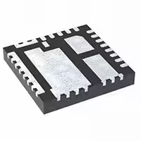
Infineon Technologies TDA21520AUMA1
- Part No.:
- TDA21520AUMA1
- Manufacturer:
- Infineon Technologies
- Category:
- Full Half-Bridge (H Bridge) Drivers
- Package:
- 25-PowerTFQFN
- Datasheet:
-
 TDA21520AUMA1.pdf
- Description:
- IFX POWERSTAGE/DRIVER PG-IQFN-25
- Quantity:
- Payment:

- Shipping:

Inventory:8,979
Please send an inquiry. Send us your inquiry, and we will respond immediately.
Product details
Overview
TDA21520AUMA1 from Infineon is a 20 A integrated power-stage DC-DC converter with synchronous buck topology, co-packaged gate driver, high-side and low-side MOSFETs, and active diode structure for DDR memory voltage regulation. It operates from 4.25 V to 16 V input, delivers 0.225–5.5 V output, supports up to 1.5 MHz switching, and features on-chip current sensing (5 µA/A gain) and thermal monitoring via TMON pin.
For engineers reviewing the TDA21520AUMA1 datasheet, TDA21520AUMA1 pinout, TDA21520AUMA1 application in DDR memory power delivery, or TDA21520AUMA1 equivalent for high-frequency buck power stages, this page provides verified electrical parameters, validated pin functions, package layout guidance, and real-world design context for embedded and server-grade memory subsystems.
Technical Context
The TDA21520AUMA1 implements a fully integrated synchronous buck power stage with internal MOSFET current sensing-replacing external DCR-based sense networks-and an active diode architecture that minimizes reverse recovery charge while achieving Schottky-like VSD. Its PWM interface accepts 3.3 V logic with tri-state control for precise dead-time management and zero-current turn-off.
Thermal protection includes junction temperature reporting (8 mV/°C slope, 0.6 V offset), cycle-by-cycle overcurrent detection, high-side short detection, and auto-replenishing bootstrap capacitor control. The device enters ultra-low-power DEEP SLEEP (32 µA) when EN is low and auto-SLEEP (1.7 mA) after 20 µs of PWM tri-state.
Key Specifications
| Parameter | Value and Actual Design Meaning |
|---|---|
| Output Current | 20 A continuous-supports high-density DDR4/DDR5 memory rail designs without external current sharing. |
| Input Voltage Range | 4.25 V to 16 V-compatible with 5 V, 12 V intermediate bus architectures in servers and networking equipment. |
| Switching Frequency | Up to 1.5 MHz-enables use of sub-300 nH inductors and compact ceramic output capacitors. |
| Current Sense Gain | 5 µA/A-provides direct analog current feedback to controller IMONREF pin with ±1% typical accuracy at 1 kΩ gain resistor. |
| Thermal Reporting | 8 mV/°C linear slope + 0.6 V offset on TMON-allows real-time junction temperature monitoring without external sensor. |
| Quiescent Current | 1.7 mA in auto-SLEEP, 32 µA in DEEP SLEEP-minimizes standby power in always-on memory subsystems. |
| Package Dimensions | 4 mm × 5 mm × 0.9 mm PQFN-optimized for low-inductance PCB layout and thermal transfer to inner copper layers. |
Pinout & Package
Package: 28-pin PQFN (4 mm × 5 mm × 0.9 mm), RoHS-compliant, exposed thermal pad (pin 15 connected to PGND).
| Pin/Terminal | Circuit Role | Design Meaning |
|---|---|---|
| 1 TMON / FLT | Analog output / fault flag | Reports junction temperature (8 mV/°C); pulled to 3.3 V during OTP, OCP, HSS, or BOOT UV. |
| 5, 27 GL | Low-side gate driver monitor | Allows oscilloscope observation of LS gate waveform without loading internal driver path. |
| 8–12 SW | Power switching node | Common drain connection of HS/LS MOSFETs; requires tight loop layout to minimize ringing. |
| 19 PHASE | Bootstrap return | AC ground reference for bootstrap capacitor; must be routed as low-inductance node adjacent to SW. |
| 20 BOOT | Bootstrap supply | Connects 0.22–0.56 µF X7R cap to PHASE; auto-refresh prevents undercharge during light-load PWM idle. |
| 21 PWM | 3.3 V logic input | Tri-state capable: High = HS on, Low = LS on, Tri-state = both off-enables precise dead-time control. |
| 22 EN | Enable control | VCC-tolerant; internal 280 kΩ pull-down ensures safe default-off state if left floating. |
| 24 IMONREF | Current sense reference | Accepts 1.1–1.9 V bias (e.g., from controller's REFOUT); sets common-mode for IMON differential output. |
| 25 IMON | Current sense output | Current-proportional analog voltage (IMON – IMONREF) × RIMON; enables accurate load current telemetry. |
| 4 VCC | Bias supply | 4.25–5.5 V logic/driver supply; requires local 1 µF ceramic decoupling to PGND. |
| 16–18 VIN | Main power input | High-current input (4.25–16 V); multiple pins reduce IR drop and improve thermal spreading. |
| 23 AGND | Signal ground | Reference for all analog pins (TMON, IMON, IMONREF, PWM, EN); must be isolated from PGND at single point. |
| 2, 7, 13–15, 26 PGND | Power ground | Low-side MOSFET source return and thermal pad connection; ties directly to PCB thermal plane. |
| 3, 28 NC | No connect | Pin 3 unconnected; pin 28 reserved for factory test-no PCB pad recommended. |
Key Features
| Feature | Design Value |
|---|---|
| Integrated active diode structure | Eliminates reverse recovery loss and enables <100 ns body diode conduction during HS dead time. |
| On-chip MOSFET current sensing | Replaces DCR sensing network-removes 2–3% efficiency penalty and layout sensitivity of inductor DCR measurement. |
| Auto-replenishing bootstrap capacitor | Maintains >4.5 V BOOT-PHASE during extended PWM tri-state periods-prevents HS FET dropout in burst-mode operation. |
| High-side MOSFET short detection (HSS) | Flags hard shorts within 100 ns-protects against catastrophic failure before controller can react. |
| Tri-state PWM interface | Enables zero-current turn-off and precise dead-time insertion without external logic or gate resistors. |
Applications
| DDR Memory Power Delivery | Server CPU Core Voltage Regulation |
|---|---|
Use Scenario: Providing tightly regulated 1.2 V / 1.1 V rails for DDR4/DDR5 DIMMs in enterprise servers with dynamic load steps up to 10 A/µs. IC Role / Device Role / Timing Role: Integrated power stage delivering fast transient response (<1 µs rise time) and accurate current telemetry to memory controller PMIC. Use Value: Enables 100% duty-cycle capability at low VOUT, reduces output capacitance by 40% vs. discrete solutions, and eliminates DCR sense drift over temperature. | Use Scenario: Supplying auxiliary low-current voltage rails (e.g., SOC I/O, PLL, or cache voltage) in multi-core CPUs where space and thermal density are constrained. IC Role / Device Role / Timing Role: Compact, high-efficiency buck stage controlled by host VR controller via PWM and IMON feedback loop. Use Value: Delivers >92% peak efficiency at 5 A/1.8 V with 4 mm × 5 mm footprint-reducing board area by 65% versus dual-MOSFET + driver discrete implementation. |
| Network Switch ASIC Power | Industrial FPGA I/O Bank Regulation |
Use Scenario: Powering 0.8–1.2 V I/O banks of high-speed switch ASICs requiring <50 mV load-step deviation and <10 µs recovery. IC Role / Device Role / Timing Role: Fast-response power stage synchronized to system clock domain; TMON pin feeds thermal margining algorithm in baseboard management controller. Use Value: Achieves 25 A/µs slew rate with <300 ns propagation delay from PWM edge to SW transition-meeting IEEE 802.3ap jitter requirements. | Use Scenario: Regulating configurable 1.2–3.3 V I/O banks in industrial FPGAs deployed in harsh environments (-40°C to +85°C ambient). IC Role / Device Role / Timing Role: Robust power stage with integrated OTP, OCP, and HSS-operating reliably across full industrial temperature range without derating. Use Value: Eliminates need for external current-sense amplifier and thermal sensor, reducing BOM count by 4 components and improving long-term calibration stability. |
Equivalent & Alternatives
The following parts are listed as comparable options for similar integrated power-stage applications.
| Alternative Part | Technical Difference | Application Difference | Selection Advice |
|---|---|---|---|
| MP86957GQZ-P | 15 A rating, 750 kHz max fSW, no IMON output, uses external current sense resistor | Lacks integrated current telemetry and thermal reporting; suited for cost-sensitive, lower-current applications without telemetry needs | Select when system-level current monitoring is handled externally and 15 A output suffices |
| TPS53679RSBT | 25 A rating, integrated controller + power stage, supports 3+2 phase interleaving, requires external IMON scaling | Controller-integrated solution with multi-phase capability; higher complexity but better transient handling for >20 A loads | Select when designing scalable multi-phase VR for high-end CPUs or GPUs |
Compared with MP86957GQZ-P and TPS53679RSBT, the TDA21520AUMA1 uniquely combines 20 A capability, on-die current sensing with IMON analog output, and real-time thermal reporting in a minimal 4×5 mm footprint-making it optimal for space-constrained, telemetry-aware DDR and ASIC power systems where discrete sensing adds cost and error.
Availability
TDA21520AUMA1 is available at Aetrix Electronics and suitable for DDR memory power delivery, server CPU auxiliary rail regulation, and high-speed network ASIC I/O supply requiring stable component supply, consistent parametric performance, and long-term lifecycle support.
Supply support for TDA21520AUMA1 includes scheduled delivery planning, volume procurement assistance, BOM continuity management, traceable sourcing, and lifecycle availability coordination for OEM customers, industrial embedded developers, connected-device designers, and electronics production programs.
Manufacturer
Infineon Technologies is a German semiconductor manufacturer specializing in power management, automotive microcontrollers, and industrial sensors, with global manufacturing and quality certification to ISO/TS 16949 and IATF 16949.
The TDA21520 belongs to Infineon's OptiMOS™ Power Stage product line, engineered specifically for high-frequency, high-efficiency DC-DC conversion in memory and processor power delivery systems where integration, thermal performance, and analog telemetry are critical.
FAQ
What is the recommended bootstrap capacitor value and dielectric type for TDA21520AUMA1?
A 0.22 µF to 0.56 µF X7R ceramic capacitor is required between BOOT and PHASE pins. X7R offers stable capacitance over voltage and temperature, essential for maintaining gate drive voltage during high-duty-cycle operation. Avoid Y5V or Z5U due to excessive capacitance loss at bias voltage.
How does the TDA21520AUMA1 achieve superior current sense accuracy compared to DCR-based methods?
It uses integrated MOSFET on-resistance sensing with matched process tracking, delivering 5 µA/A gain and ±1% typical accuracy across -40°C to +125°C. Unlike DCR sensing-which suffers from inductor tolerance, temperature drift, and PCB layout parasitics-this method eliminates external components and maintains accuracy without calibration.
Can the TDA21520AUMA1 operate with a 3.3 V-only supply, or is a separate 5 V VCC required?
VCC must be supplied with 4.25–5.5 V; it cannot be powered from 3.3 V. The internal gate driver and logic require ≥4.25 V for reliable high-side MOSFET turn-on and UVLO margin. A dedicated 5 V bias rail-decoupled with 1 µF ceramic-is mandatory per datasheet Section 4.3.
What is the function of the GL pin, and is it required for normal operation?
GL (Gate Low-side) is a buffered low-side gate driver output provided for diagnostic probing only. It is not required for functional operation-no external connection is needed. Connecting an oscilloscope to GL allows non-invasive observation of LS gate timing without affecting internal driver performance or adding capacitive load.
TDA21520AUMA1 Specifications
- Product attributes
- Attribute value
- Manufacturer:
- Infineon Technologies
- Series:
- EiceDRIVER™
- Package/Case:
- 25-PowerTFQFN
- Packaging:
- Tape & Reel (TR)
- Product Status:
- Active
- Output Configuration:
- -
- Applications:
- -
- Interface:
- -
- Load Type:
- -
- Technology:
- -
- Rds On (Typ):
- -
- Current - Output / Channel:
- -
- Current - Peak Output:
- -
- Voltage - Supply:
- 4.25V ~ 16V
- Voltage - Load:
- -
- Operating Temperature:
- -40°C ~ 125°C (TJ)
- Grade:
- -
- Qualification:
- -
- Features:
- -
- Fault Protection:
- -
- Mounting Type:
- Surface Mount
- Supplier Device Package:
- PG-IQFN-25-1
TDA21520AUMA1 FAQ
1.How can I place an order for TDA21520AUMA1 through Aetrix?
Please submit a Request for Quotation (RFQ) for TDA21520AUMA1 on Aetrix. Our sales agent will provide a competitive quotation and guide you through the order confirmation once you accept the terms.
2.Are the price and stock information for TDA21520AUMA1 reliable?
The price and inventory of TDA21520AUMA1 are updated periodically and may fluctuate due to market conditions. Stock and pricing data are typically refreshed every 24 hours. Quotation validity for TDA21520AUMA1 is usually 5 days.
3.What payment methods are accepted for TDA21520AUMA1?
We accept Wire Transfer, PayPal, Credit Card, Western Union, MoneyGram, and Escrow for TDA21520AUMA1 transactions.
Note: Certain payment methods may incur a processing fee.
4.How is shipping managed for TDA21520AUMA1?
TDA21520AUMA1 orders can be shipped via leading logistics carriers, including DHL, UPS, FedEx, TNT, or Registered Mail.
Once your TDA21520AUMA1 order is processed, you will receive an email with the shipment details and tracking number.
Note: Tracking information may take up to 24 hours to appear. Express delivery typically takes 3–5 business days.
5.How can I obtain technical support or documentation for TDA21520AUMA1?
For technical support, including TDA21520AUMA1 datasheets, pinout diagrams, or application guidance, please contact our engineering support team. They can provide detailed documentation and assistance for your TDA21520AUMA1 requirements.
6.How does Aetrix verify that TDA21520AUMA1 is sourced from the original manufacturer or authorized distributors?
All TDA21520AUMA1 products on Aetrix are procured from qualified distributors and authorized channels. Our dedicated quality assurance team conducts strict verification, including traceability checks and, if necessary, third-party testing. This ensures that TDA21520AUMA1 meets industry standards.
7.What is the process for return or replacement of TDA21520AUMA1?
All TDA21520AUMA1 units undergo pre-shipment inspection (PSI). If there is an issue with TDA21520AUMA1, returns or replacements are accepted under the following conditions:
1.Quantity discrepancies, incorrect items, or visible external defects (such as breakage or corrosion), acknowledged by Aetrix.
2.The issue is reported within 90 days of delivery.
3.The TDA21520AUMA1 part is unused and in its original packaging.
Return procedure for TDA21520AUMA1:
1.Submit a request within 90 days.
2.Obtain a Return Material Authorization (RMA) from Aetrix.
TDA21520AUMA1 Tags

-
NCP1393BDR2G
onsemi
-
A3909GLNTR-T
Allegro MicroSystems
-
NCP51530BDR2G
onsemi
-
A3909GLYTR-T
Allegro MicroSystems
-
SIC631CD-T1-GE3
Vishay Siliconix
-
BTN70301EPAXUMA1
Infineon Technologies

-
TDA21520AUMA1
Infineon Technologies
-
AOZ5116QI
Alpha & Omega Semiconductor Inc.
-
IRSM005-301MHTR
Infineon Technologies
-
IRSM005-301MH
Infineon Technologies
-
MP6610GJ-Z
Monolithic Power Systems Inc.

-
DRV8908QPWPRQ1
Texas Instruments
Tech Hub

Operational amplifier guide covering op amp basics, feedback, ideal vs real op amps, common configurations, buffer circuits, offset, bias current, gain-bandwidth, slew rate, rail-to-rail limits and sel…

Jumper cables guide covering safe connection order, red and black clamp placement, final ground connection, cable gauge, length, clamp quality, copper vs CCA cables, jump starter comparison and battery…

LDO regulator guide covering low dropout voltage, power dissipation, thermal design, PSRR, output noise, capacitor stability, adjustable LDO circuits, LDO vs buck converter and datasheet selection chec…

Conditional Access Module guide covering CAM meaning, CI/CI+ interface, smart card authorization, DVB security workflow, TV and set-top box compatibility, internal electronics, ESD protection, connecto…

Guide to electronic component obsolescence covering EOL risk, PCN/PDN notices, last-time buy planning, replacement options, form-fit-function validation, counterfeit risk and BOM lifecycle management.

18650 battery guide covering lithium-ion cell basics, 3.6V/3.7V voltage, 4.2V charging, mAh and Wh capacity, protected cells, chargers, BMS, series-parallel packs, holders, welding and sourcing checks.…

Hall effect sensor guide covering working principle, linear and digital sensors, Arduino circuits, current sensing, speed detection, automotive applications, A3144 examples, signal filtering and datash…

Product Change Notification guide for electronic components, covering PCN meaning, PCN vs PDN/EOL, common change types, risk levels, form-fit-function review, engineering validation, BOM control, LTB/L…

A practical guide to blend door actuators, covering HVAC function, symptoms, location, AC and heater issues, reset and calibration, replacement cost, electrical diagnosis, compatibility checks, and rep…

Engineering guide to Raspberry Pi alternatives, covering chip-level differences, Orange Pi, ROCK, Jetson, Banana Pi, NanoPi, Compute Module, Pico, GPIO, camera, HAT compatibility, and replacement risks…


