Infineon Technologies SKB15N60E8151
- Part No.:
- SKB15N60E8151
- Manufacturer:
- Infineon Technologies
- Category:
- Single IGBTs
- Package:
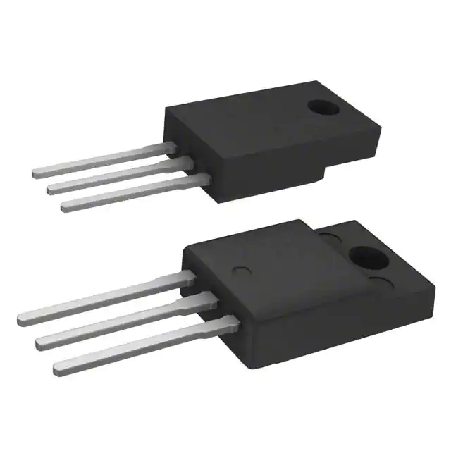
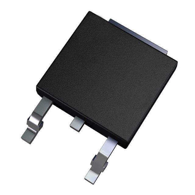
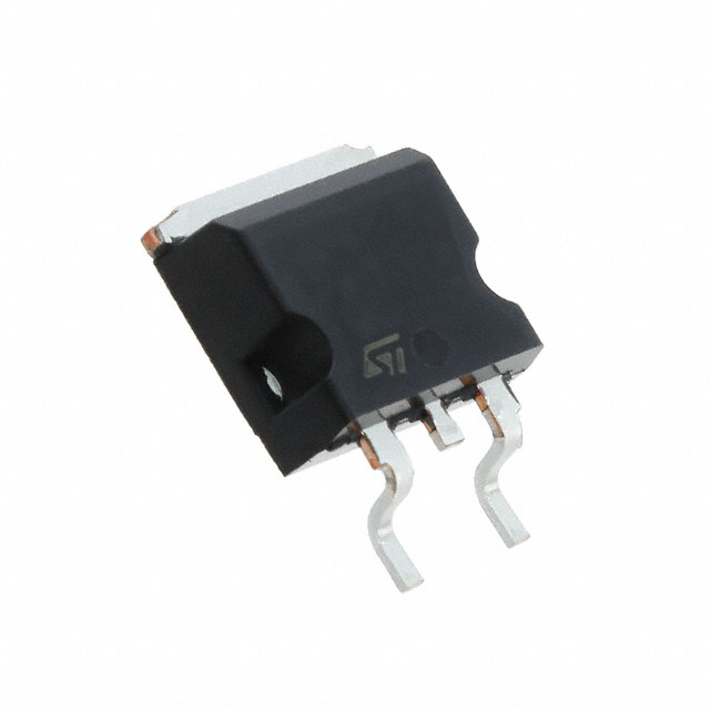
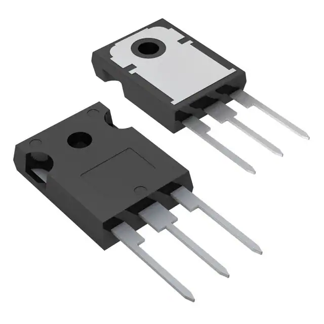
- TO-263-3, D2PAK (2 Leads + Tab), TO-263AB
- Datasheet:
-
 SKB15N60E8151.pdf
- Description:
- IGBT NPT 600V 31A TO263-3
- Quantity:
- Payment:

- Shipping:

Inventory:1,288
Please send an inquiry. Send us your inquiry, and we will respond immediately.
Product details
Overview
SKB15N60E8151 from Infineon Technologies is a 600V N-channel IGBT in NPT technology designed for high-voltage switching, motor-drive power stages, inverter circuits, switch-mode power supplies, UPS systems, welding equipment, and industrial power conversion. The device is supplied in a surface-mount TO-263 / D2PAK package and integrates an anti-parallel fast recovery diode for inductive-load and bridge-leg applications.
As part of the Infineon SKB15N60 fast IGBT family, SKB15N60E8151 combines 600V collector-emitter blocking voltage, 31A collector-current capability, low saturation voltage, 15A nominal switching test current, 139W power dissipation, and fast switching behavior in a compact surface-mount power package. For engineers reviewing the SKB15N60E8151 datasheet, SKB15N60E8151 pinout, SKB15N60E8151 application, or SKB15N60E8151 equivalent, this device is widely used in industrial inverters, power supplies, motor drives, induction heating, lamp ballasts, and medium-power high-voltage switching circuits.
Technical Context
In power-conversion circuits, SKB15N60E8151 operates as a high-voltage insulated-gate bipolar transistor. The gate is voltage-driven like a MOSFET, while the main conduction path provides the saturation-voltage behavior typical of IGBTs. This makes the device useful in applications where switching voltage is high and conduction loss must be evaluated through VCE(sat), not RDS(on).
The device uses NPT IGBT technology and includes a soft, fast recovery anti-parallel diode. This diode is important in motor drives, half-bridge converters, full-bridge inverters, and other inductive-load circuits where current must continue flowing when the IGBT turns off or when the bridge polarity changes.
SKB15N60E8151 should be driven with an appropriate gate-driver circuit, commonly using a positive gate voltage near 15V for full enhancement and a controlled gate resistor to manage switching speed, EMI, and turn-off behavior. System design should verify switching energy, thermal resistance, diode recovery behavior, collector current, gate charge, heatsinking, and safe operating area under the actual bus voltage and load profile.
Key Specifications
| Parameter | Value and Actual Design Meaning |
|---|---|
| Device Type | N-channel insulated-gate bipolar transistor with integrated anti-parallel fast recovery diode. |
| Technology | Fast IGBT in NPT technology for high-voltage switching applications. |
| Collector-Emitter Voltage | 600V VCES rating for high-voltage DC bus and offline power-conversion systems. |
| Collector Current | 31A maximum collector current rating under package and thermal conditions. |
| Pulsed Collector Current | 62A pulsed current rating for transient switching conditions within safe operating limits. |
| Nominal Test Current | 15A commonly used in datasheet switching and saturation-voltage conditions. |
| Collector-Emitter Saturation Voltage | 2.4V maximum at VGE = 15V and IC = 15A at 25°C, defining conduction-loss behavior. |
| Switching Energy | Approximately 0.57mJ total switching energy under typical datasheet inductive-load test conditions. |
| Gate Charge | Approximately 76nC total gate charge, affecting gate-driver current demand and switching speed. |
| Power Dissipation | 139W maximum power dissipation with proper thermal mounting and case-temperature conditions. |
| Anti-Parallel Diode | Integrated fast recovery diode supports inductive current freewheeling and bridge-leg operation. |
| Operating Junction Temperature | Up to 150°C maximum junction temperature for power-stage thermal design. |
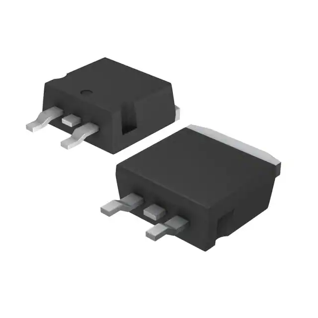
| Package | TO-263AB / D2PAK surface-mount power package, also referenced as PG-TO263-3-2. |
| Mounting Type | Surface-mount power package with collector-connected tab for PCB copper and thermal management. |
Pinout & Package
The SKB15N60E8151 pinout follows the TO-263 / D2PAK IGBT package format. The main terminals are gate, collector, and emitter. The large tab is electrically connected to the collector, so PCB copper, heatsink contact, and creepage spacing must be designed with the high-voltage collector potential in mind.
For PCB implementation, the collector current path and emitter return path should use low-inductance routing. The gate loop should be short and include a suitable gate resistor close to the device. Kelvin-style emitter routing for the gate-driver return is preferred where possible to reduce switching noise, false triggering, and gate-emitter voltage ringing.
| Pin / Function | PCB Design and Circuit Role |
|---|---|
| Gate | Voltage-control terminal driven by an external IGBT gate driver; gate resistance controls switching speed and EMI. |
| Collector | Main high-voltage terminal connected to the DC bus, switching node, or load-side power path. |
| Emitter | Main current return terminal and gate-drive reference node; layout strongly affects switching stability. |
| Collector Tab | Large D2PAK tab connected to the collector for electrical and thermal conduction. |
| Anti-Parallel Diode Path | Provides reverse current flow path from emitter to collector in inductive and bridge applications. |
| TO-263 / D2PAK Package | Surface-mount power package requiring thermal copper area, proper solder joint quality, and high-voltage spacing. |
Key Features
- 600V N-channel IGBT for high-voltage switching applications.
- NPT technology supports fast switching and rugged power-conversion operation.
- Integrated fast recovery anti-parallel diode for inductive-load circuits.
- 31A collector-current capability with proper thermal design.
- Low VCE(sat) behavior supports reduced conduction loss at rated operating current.
- Surface-mount TO-263 / D2PAK package supports compact power PCB assembly.
- Suitable for motor drives, inverters, SMPS, UPS, and industrial power stages.
- Gate-controlled device compatible with standard IGBT gate-driver circuits.
- Collector-connected tab provides thermal path but requires high-voltage layout clearance.
Applications
| Motor Drives & Inverters | Switch-Mode Power Supplies |
|---|---|
|
Use Scenario: Industrial motor drives, inverter bridge legs, fan drives, pump drives, and actuator power stages. Device Role: SKB15N60E8151 switches high-voltage DC bus current and provides diode freewheeling support for inductive loads. Use Value: Combines IGBT switching capability and anti-parallel diode behavior in one surface-mount power device. |
Use Scenario: Offline SMPS, high-voltage DC-DC converters, auxiliary power supplies, and industrial supply modules. Device Role: Operates as the main high-voltage switching device in converter power stages. Use Value: Supports 600V switching margin and gate-controlled power conversion. |
| UPS, Welding & Industrial Power | Induction Heating & Lamp Ballasts |
|
Use Scenario: UPS inverters, welding power stages, industrial converters, and high-energy switching systems. Device Role: Handles repetitive switching under controlled gate-drive and thermal conditions. Use Value: Provides a compact D2PAK power switch for medium-power converter designs. |
Use Scenario: Resonant converters, induction heating stages, lighting ballasts, and high-voltage switching circuits. Device Role: Switches high-voltage current while the integrated diode supports reverse recovery requirements in resonant or inductive circuits. Use Value: Helps reduce external diode count and supports compact high-voltage switching layouts. |
Equivalent & Alternatives
When evaluating SKB15N60E8151 equivalent devices, engineers should compare collector-emitter voltage, continuous and pulsed collector current, VCE(sat), switching energy, diode recovery behavior, gate charge, package footprint, tab connection, thermal resistance, and product lifecycle status.
| Alternative Part | Technical Difference | Application Difference | Selection Advice |
|---|---|---|---|
| SKB15N60ATMA1 | Related Infineon SKB15N60 D2PAK ordering option with similar 600V IGBT positioning and different ordering or compliance status. | Used in similar surface-mount high-voltage IGBT power stages. | Choose SKB15N60E8151 when the existing BOM, package marking, and legacy qualification require this exact orderable option. |
| IKB15N60T | Infineon 600V IGBT from a later TRENCHSTOP family with different switching, conduction, package, and dynamic behavior. | Used in updated inverter and converter designs requiring different loss tradeoffs. | Choose SKB15N60E8151 when the circuit and gate-drive behavior are already qualified around the SKB15N60 NPT device. |
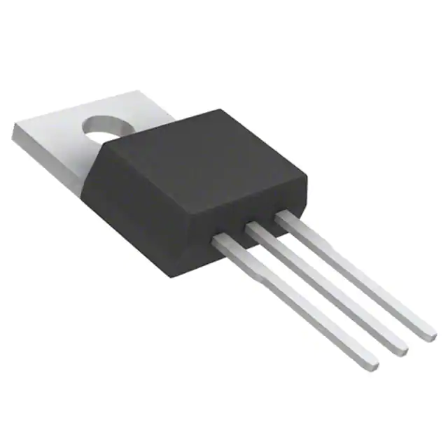
| IKP15N60T | Through-hole TO-220 style 600V IGBT alternative with different mounting and thermal path. | Used where a heatsink-mounted through-hole package is preferred instead of D2PAK surface mount. | Choose SKB15N60E8151 when the PCB is designed for TO-263 / D2PAK surface-mount assembly. |
| FGA15N60 | 600V class IGBT alternative from another manufacturer with different VCE(sat), switching energy, diode behavior, and package options. | Used in similar medium-power inverter and power-supply applications after full electrical review. | Choose SKB15N60E8151 when Infineon device behavior, D2PAK footprint, and existing production approval must be maintained. |
Compared with IKB15N60T, SKB15N60E8151 is a legacy Infineon NPT IGBT option in a D2PAK surface-mount package, so substitution should not be based on voltage and current ratings alone. SKB15N60E8151 vs IKP15N60T selection depends mainly on package style, thermal mounting method, gate-drive qualification, switching-loss target, diode recovery behavior, and PCB footprint compatibility.
Quality
SKB15N60E8151 should be sourced as original Infineon Technologies components through traceable and controlled supply channels. Quality verification procedures may include package inspection, top-mark validation, solderability testing, gate leakage testing, collector-emitter leakage testing, VCE(sat) verification, diode forward-voltage testing, switching-function checks, and incoming inspection according to power semiconductor production requirements.
Because the device is used in high-voltage switching applications, reliability depends on correct gate-drive voltage, turn-off control, desaturation or overcurrent protection, snubber design, thermal-path design, collector-tab insulation or spacing, PCB creepage and clearance, and validation under worst-case load, temperature, and switching conditions. Traceable sourcing supports manufacturing quality and reduces counterfeit supply-chain risk for obsolete or legacy IGBT production programs.
Availability
SKB15N60E8151 available at Aetrix Electronics and suitable for motor drives, industrial inverters, switch-mode power supplies, UPS systems, welding equipment, induction heating, lamp ballasts, and high-voltage switching circuits requiring stable component supply and repeatable production support.
Supply support may include scheduled delivery planning, volume procurement support, legacy BOM sourcing, traceable sourcing management, and long-term availability support for OEM manufacturers, industrial-control developers, power-supply designers, repair programs, and electronics production operations.
For production deployment, confirming voltage rating, current rating, VCE(sat), diode recovery behavior, D2PAK footprint, thermal design, gate-drive compatibility, lifecycle status, and sourcing continuity helps reduce procurement risk and improve manufacturing stability.
Manufacturer
Infineon Technologies is a semiconductor manufacturer specializing in power semiconductors, microcontrollers, sensors, security ICs, automotive electronics, industrial power devices, MOSFETs, IGBTs, gate drivers, and power-management solutions for automotive, industrial, communication, consumer, and energy applications.
The Infineon IGBT portfolio focuses on high-voltage switching, inverter power stages, motor-drive efficiency, rugged gate-controlled power devices, integrated diode options, package flexibility, and reliable power conversion for industrial drives, renewable energy, UPS systems, welding equipment, and switch-mode power supplies.
FAQ
What is SKB15N60E8151 used for?
SKB15N60E8151 is used for high-voltage switching in motor drives, industrial inverters, switch-mode power supplies, UPS systems, welding equipment, induction heating, lamp ballasts, and other medium-power converter circuits.
Where can I find the SKB15N60E8151 datasheet download?
The SKB15N60E8151 datasheet is available from Infineon and authorized distributor archives, and includes collector-emitter voltage, collector current, saturation voltage, switching energy, diode characteristics, thermal ratings, package drawing, and recommended operating information.
What should be considered in SKB15N60E8151 PCB design?
PCB implementation should prioritize low-inductance collector and emitter current paths, short gate routing, correct gate resistor placement, strong thermal copper, adequate creepage and clearance, controlled switching-node layout, and proper handling of the collector-connected D2PAK tab.
Does SKB15N60E8151 include an anti-parallel diode?
Yes. SKB15N60E8151 includes an integrated anti-parallel fast recovery diode, which supports inductive-load freewheeling and inverter bridge operation.
What are common SKB15N60E8151 equivalent solutions?
Common alternatives include SKB15N60ATMA1, IKB15N60T, IKP15N60T, and selected 600V 15A-class IGBTs from other manufacturers depending on package, VCE(sat), switching loss, diode recovery, gate charge, thermal behavior, and sourcing continuity.
SKB15N60E8151 Specifications
- Product attributes
- Attribute value
- Manufacturer:
- Infineon Technologies
- Series:
- -
- Package/Case:
- TO-263-3, D2PAK (2 Leads + Tab), TO-263AB
- Packaging:
- Bulk
- Product Status:
- Active
- IGBT Type:
- NPT
- Voltage - Collector Emitter Breakdown (Max):
- 600 V
- Current - Collector (Ic) (Max):
- 31 A
- Current - Collector Pulsed (Icm):
- 62 A
- Vce(on) (Max) @ Vge, Ic:
- 2.4V @ 15V, 15A
- Power - Max:
- 139 W
- Switching Energy:
- 570µJ
- Input Type:
- Standard
- Gate Charge:
- 76 nC
- Td (on/off) @ 25°C:
- 32ns/234ns
- Test Condition:
- 400V, 15A, 21Ohm, 15V
- Reverse Recovery Time (trr):
- 279 ns
- Operating Temperature:
- -55°C ~ 150°C (TJ)
- Grade:
- -
- Qualification:
- -
- Mounting Type:
- Surface Mount
- Supplier Device Package:
- PG-TO263-3-2
SKB15N60E8151 FAQ
1.How can I place an order for SKB15N60E8151 through Aetrix?
Please submit a Request for Quotation (RFQ) for SKB15N60E8151 on Aetrix. Our sales agent will provide a competitive quotation and guide you through the order confirmation once you accept the terms.
2.Are the price and stock information for SKB15N60E8151 reliable?
The price and inventory of SKB15N60E8151 are updated periodically and may fluctuate due to market conditions. Stock and pricing data are typically refreshed every 24 hours. Quotation validity for SKB15N60E8151 is usually 5 days.
3.What payment methods are accepted for SKB15N60E8151?
We accept Wire Transfer, PayPal, Credit Card, Western Union, MoneyGram, and Escrow for SKB15N60E8151 transactions.
Note: Certain payment methods may incur a processing fee.
4.How is shipping managed for SKB15N60E8151?
SKB15N60E8151 orders can be shipped via leading logistics carriers, including DHL, UPS, FedEx, TNT, or Registered Mail.
Once your SKB15N60E8151 order is processed, you will receive an email with the shipment details and tracking number.
Note: Tracking information may take up to 24 hours to appear. Express delivery typically takes 3–5 business days.
5.How can I obtain technical support or documentation for SKB15N60E8151?
For technical support, including SKB15N60E8151 datasheets, pinout diagrams, or application guidance, please contact our engineering support team. They can provide detailed documentation and assistance for your SKB15N60E8151 requirements.
6.How does Aetrix verify that SKB15N60E8151 is sourced from the original manufacturer or authorized distributors?
All SKB15N60E8151 products on Aetrix are procured from qualified distributors and authorized channels. Our dedicated quality assurance team conducts strict verification, including traceability checks and, if necessary, third-party testing. This ensures that SKB15N60E8151 meets industry standards.
7.What is the process for return or replacement of SKB15N60E8151?
All SKB15N60E8151 units undergo pre-shipment inspection (PSI). If there is an issue with SKB15N60E8151, returns or replacements are accepted under the following conditions:
1.Quantity discrepancies, incorrect items, or visible external defects (such as breakage or corrosion), acknowledged by Aetrix.
2.The issue is reported within 90 days of delivery.
3.The SKB15N60E8151 part is unused and in its original packaging.
Return procedure for SKB15N60E8151:
1.Submit a request within 90 days.
2.Obtain a Return Material Authorization (RMA) from Aetrix.
SKB15N60E8151 Tags
;;2.jpg)
-
STGD3NB60SDT4
STMicroelectronics

-
HGTD1N120BNS9A
onsemi
-
STGF7NB60SL
STMicroelectronics
-
FGD5T120SH
onsemi
-
STGB3NC120HDT4
STMicroelectronics
-
IKP20N60TXKSA1
Infineon Technologies
-
STGW30H60DFB
STMicroelectronics
-
STGB30M65DF2
STMicroelectronics
-
IKB20N60TATMA1
Infineon Technologies
-
STGB30V60DF
STMicroelectronics
-
IKW30N60DTPXKSA1
Infineon Technologies
-
ISL9V3040P3
onsemi
Tech Hub
Amplifier guide covering voltage, current and power amplification, gain, feedback, amplifier classes, audio and RF applications, op-amp circuits, transimpedance amplifiers, datasheet selection and trou…

Machine vision system guide covering components, inspection workflow, camera and lens selection, FOV, pixel resolution, motion blur, strobe lighting, bandwidth, 2D/3D vision, integration, troubleshooti…
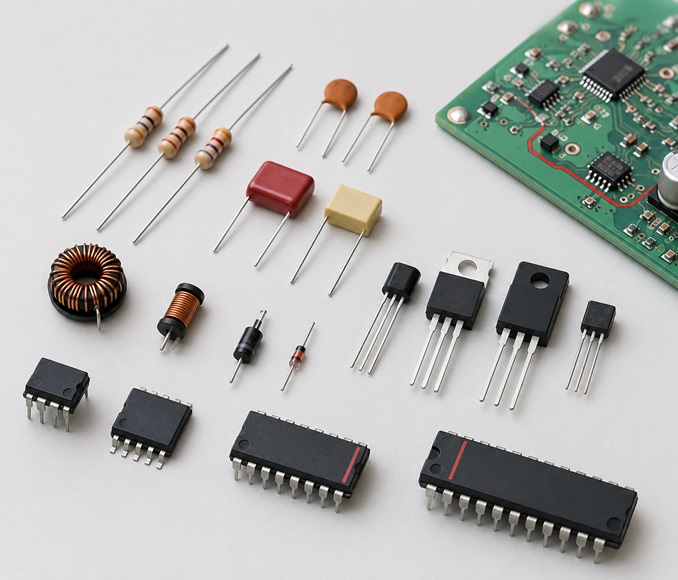
Electronic devices and circuits guide covering passive components, semiconductors, analog and digital circuits, circuit theory, practical calculations, troubleshooting, datasheet selection, and learnin…
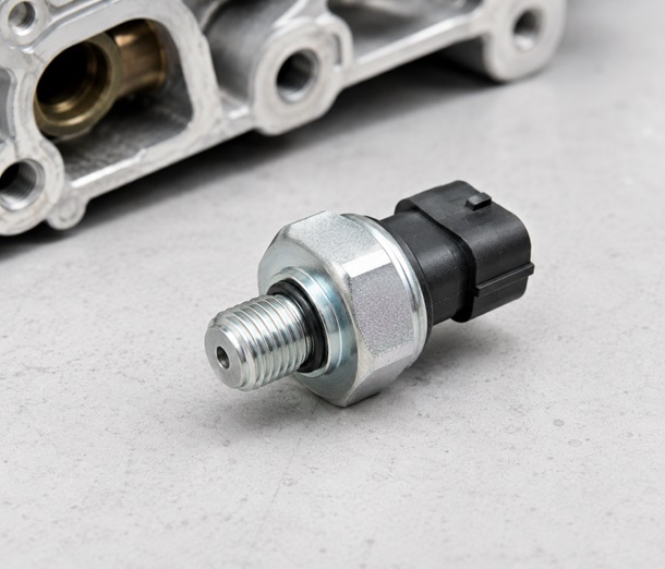
Oil pressure sensor diagnosis covering symptoms, location, testing, replacement, socket access, common failure cases, and the electronic signal path between the pressure sensor, wiring, ECU and gauge s…
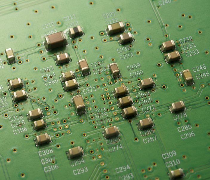
MLCC ESR, impedance and self-resonant frequency in decoupling networks. Covers PDN behavior, frequency response, measurement methods, failure cases and practical capacitor selection for power integrity…
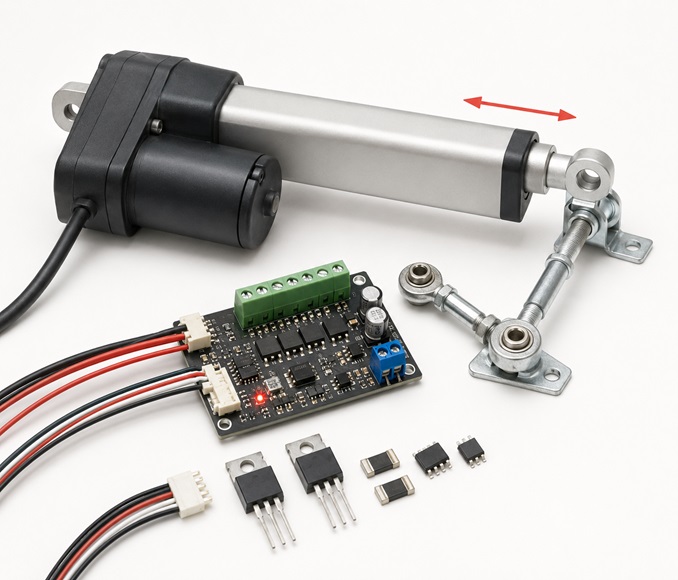
An actuator converts a control signal and energy source into mechanical motion. This guide explains actuator types, working principles, electric and linear actuators, automotive use cases, troubleshoot…
A potentiometer is a three-terminal adjustable resistor used for voltage division, analog control, calibration and signal adjustment. This guide explains wiring, symbols, types, 10k values, digital pot…
An FPGA is reconfigurable digital hardware used for custom logic, parallel processing, low-latency I/O and interface control. This guide explains FPGA meaning, architecture, boards, programming flow, a…
A logic gate is a basic digital circuit that uses Boolean logic to convert binary inputs into one output. This guide explains AND, OR, NOT, NAND, NOR, XOR, truth tables, universal gates, logic ICs and …

A mass air flow sensor, often called a MAF sensor, measures the amount of air entering an engine.